| By | Casey Muratori |
Code and Scale
First I’d like to address two questions from Sean Barrett, who of course gets special treatment here because he is a founding member of Wild Wednesday, and that confers upon him special request-priority privileges. First, he wanted to know precisely what code I was using to create the pattern, because as he (correctly) pointed out, in my rush to get the article out before it became Witness Saturday, I had neglected to include the relevant details.
So here is (almost literally) the code I used to generate the staggered concentric intersection pattern:
{
{
}
}
Obviously, for suitably small values of PointRadius, the lazy constant “128” for the number of circles to check would have to be increased. Better yet, if one were a super duper programmer — like, we’re talking healthcare.gov-level programmers here — you could even change the for loops to properly compute the starting and ending radii from the first intersection with the sample region (major hint for programmers who aren’t quite at that vaulted tier yet: the minimum and maximum distance from a point to an axis-aligned box in any number of dimensions can be computed separably).
I did not include the circle intersection routine, because it is not specific to this algorithm. Whatever circle intersection you have lying or download off the net will compute the necessary pair of points.
Here is a diagram that shows the circles themselves overlaid on top of the concentric intersection and staggered concentric intersection:
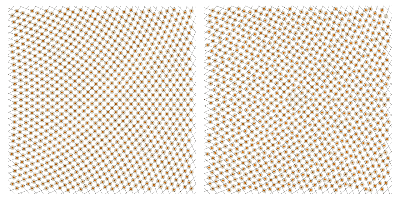
As you can see, both circles are placed to the left of the pattern region, with one circle above and one circle below. I picked these locations because I wanted dual curvature (as explained in the previous article), so my intention was to place the circles such that their arcs would combine to form a curving grid.
In addition to being interested in the specifics, Sean was also wondering if the pattern would work for larger scales of patterns, meaning (I’m assuming) that the pattern should be able to cover a very large region and still look good everywhere. At one point he even used the word “infinite”.
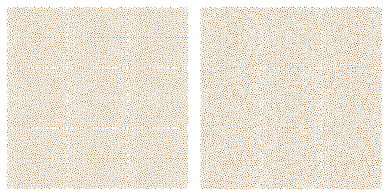
To answer that, first I would point out that really, you can make a fairly large pattern without actually changing this setup in any way. All you have to do is change the PointRadius parameter in the code to something smaller. This will properly adjust the radial stepping to produce a denser “circle intersection grid”. Here is what it looks like with a 0.009, for example:
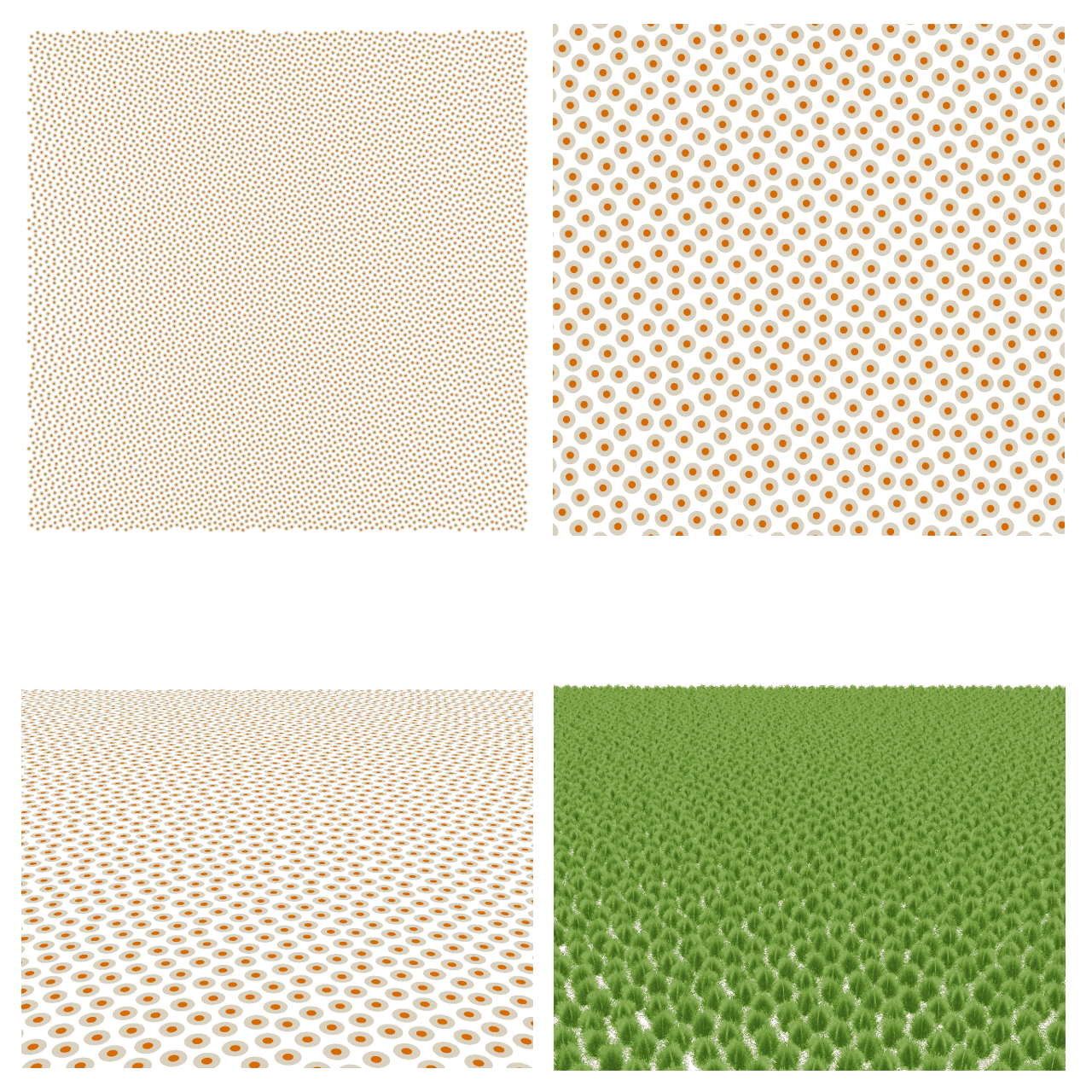
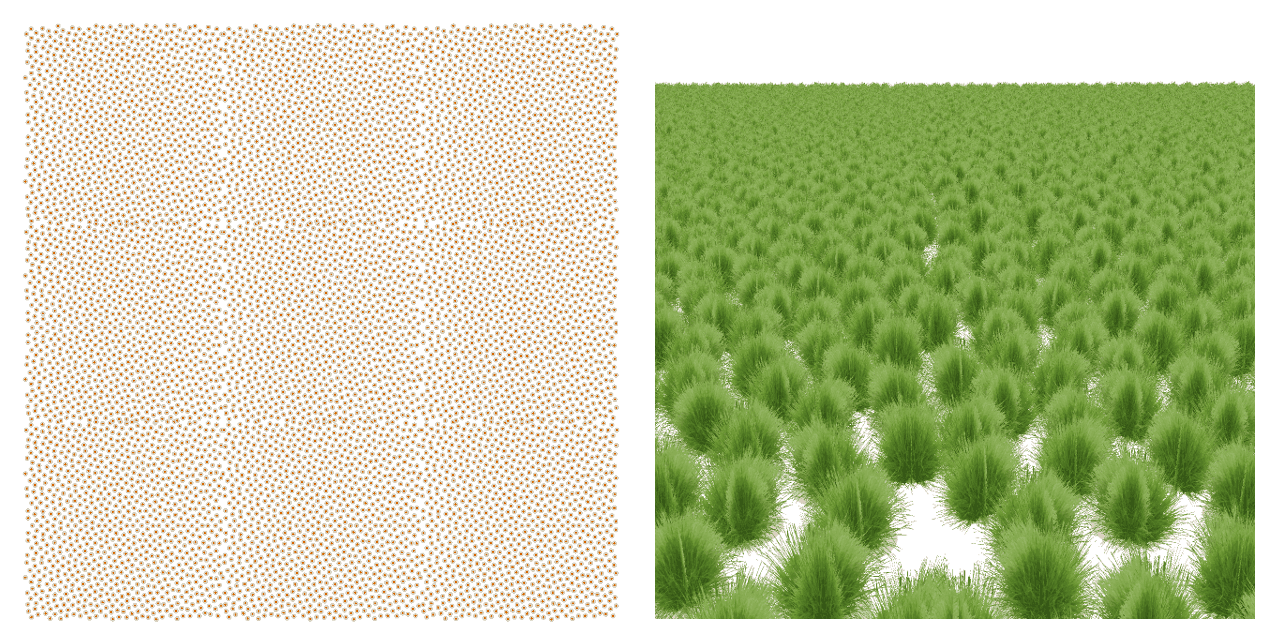
And here’s 0.005, standing right on the ground so you can see what a large expanse of the pattern would look like locally to a player:
Somewhere around that density, my crappy test app stops being competent enough to really render that much grass at a reasonable speed.
Because all the points are generated from the intersections of circles, I would have assumed that the pattern would degrade more rapidly as the density was increased. However, for reasons that I don’t yet understand but that would presumably be clear upon further study, the staggering appears to make the pattern hold up more robustly. How far this extends, I’m not sure, but based on my brief testing it clearly does not break down even at densities far greater than any single patch of grass we would ever generate in something like The Witness, where ground cover is localized to regions that contain around 8000 points or so.
As for that dirty word “infinite”, I’m afraid I don’t have much insight to offer there, as I only just discovered this pattern on Friday and I spent the weekend playing Faster than Light: Advanced Edition and a beta build of Daniel Benmergui’s Ernesto in between diabetic naps induced by old-fashioned glazed donuts (Sunday was donut day). I admit that these activities did not advance the state of the art in computer graphics as much as if I had actually sat down and done some work, but at the same time, these games aren’t exactly going to play themselves, people!
That said, for infinite patterns, the simple procedure of just sampling the pattern everywhere definitely doesn’t work. Because it is based on circles, once you are in a region where the intersections of circular curvature is unfavorable, the pattern will break. Here is the original pattern extended rightward for another three squares, for example:
That is not fancy at all, and I think it’s safe to say that no one should use that kind of pattern for mission-critical websites like healthcare.gov.
Now, if I was tasked with making an infinite generator for this pattern, I’d probably try two separate avenues of exploration and see where I get. The first would be to analyze a pleasing portion of the pattern (some subset of the [-1,1] square), determine the what the relative point locations were, and see if I could regularize it into something periodic. My guess is that this would be very difficult, because “the problem with curvature is that it’s always curving”, for lack of a better way to say it, so it seems to me that the requirement for dual curvature is such that it precludes an easy attempt to regularize it. Similarly, I might increase the density dramatically and then look at a very small region, to see what it looks like when the arcs of the circles are essentially linear. Is it still a useful pattern? What fails? Can the failures be corrected?
The second avenue would be to investigate curves that were not circles. The problem with circles is that they have a finite size, so they necessarily induce change on a scale related to their radii. There are curvatures that go on forever without even inducing a major change, such as a sine wave, where one axis can be extended infinitely while the curvature repeats. The difficulty I see in this approach is that any periodic curve is going to have inflection points at different orders, such as the crest of a sine wave or its axis-crossing point, which I fear would produce gaps or clumps of some kind in the pattern since the qualities of the curvature are weak around those points.
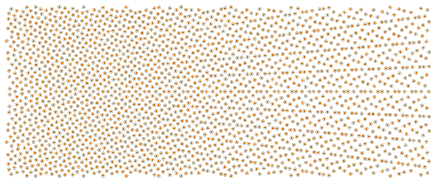
The secret, unannounced third avenue I’d investigate if both those two avenues failed would be to figure out some way to “tile” this pattern. As an example, here is the tile repeated 9 times:
On the left is the full pattern repeated 9 times, and on the right is a slightly cropped version of the pattern repeated 9 times. As you can see, it’s not inconceivable that one could create a fixup for the seams and produce a stable tiling pattern here. From the grounds-eye view, there’s not that much of an apparent abberation of the pattern at the seam, so it could be within the realm of possibility that a fixup near edges would be all that’s required to “go infinite”:
Whether or not such a fixup actually is possible, or whether the results would garner the coveted rating of “fine” from Sean, are questions that will have to wait for another day.
Scalloping and a Bird’s Eye View
Multiple people wrote in to ask about the “scalloping” artifacts and whether or not these would be problematic from a higher vantage point. One of these people was Jon Olick, whom I remembered because I’ve corresponded with him before. I apologize for not remembering the other people who commented, but let’s face it, it’s really your responsibility to be a memorable person, and obviously you failed at that. It’s nothing personal. Just try to be a bit more memorable next time. Perhaps include one of those “Up Close and Personal” videos like they show during the Olympics, so I can get a feel for the hardships and struggles that brought you to the point where you wrote me an e-mail. You know… the human element.
Anyway, I think perhaps people got the wrong impression from the first article about the quality of this pattern. At the risk of putting words into everyone’s mouths and then telling them that those words are wrong, I would like to argue that the pattern is actually much better than people thought it was.
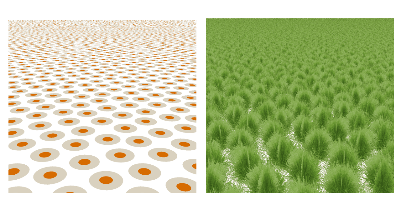
Because I was working on coverage, I intentionally rendered dark green grass sprites against a pure white background, so I could explicitly see where the coverage was breaking down. This is because coverage is a lot more about how things look in motion than it is about still images, so to save myself from having to extensively “walk around” every pattern to see how nicely it parallaxed or how often I saw objectionable rows, I intentionally rendered things to accentuate gaps in coverage when viewing a single point of view. I strongly suspect that nobody would have noticed artifacts at all if I had rendered the shots against a ground texture, like this:
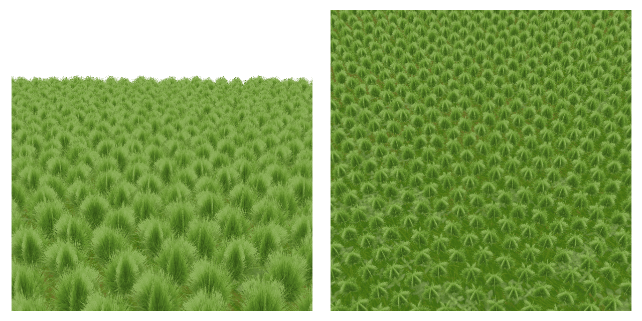
Obviously, the pattern is the same, so the scalloping is still there, and since you’re aware of it, you can certainly find it again. But hopefully you will agree that it’s difficult to notice when presented against a ground texture. It’s extremely subtle. To some degree, this even holds true when the pattern is viewed from above, as shown on the right hand side of the image. This surprised even me, as I thought the pattern would be more obvious when viewed from high vantage points, since that was not a goal of this endeavor and I was never measuring that aspect of the pattern explicitly. But the truth is that it is only blatantly obvious when viewed against a very high-contrast background, which presumably you would not be doing in any real-world usage. The most immediately objectionable artifact for bird’s-eye views when viewed against a reasonable ground texture is, honestly, the flatness of the sprite cards, since I’m not doing anything in this test harness to handle the case where they’re viewed at a steep angle. But even ignoring that and focusing on the distribution, I still can’t see much in the way of objectionable artifacts from this pattern in overhead images unless I turn off the ground. Furthermore, usually in games the rendering engine doesn’t render ground cover when you’re far away from the terrain like you would be in any situation where you could look at the grass from this kind of angle.
That said, the pattern definitely looks less random when viewed from above, and I find that it is easier for wiggly lines in the pattern to jump out at you and so on. So if the visual quality of the pattern when viewed from above was a primary concern, I suspect blue noise would still be the smartest option.
Other Patterns
Won Chun, world’s most voracious reader and veritable walking compendium of computer science literature, wrote in shortly after my article went live to say that the final pattern reminded him of “phyllotaxis and Fermat spirals”. For those of you who don’t know what “phyllotaxis” is — a set of people that included me until I just now typed it into Wikipedia — it’s the fancy word for how the leaves grow on a plant. Fermat spirals are related in that they have been used to create patterns that resemble those found in real plants, such as the pattern found on a sunflower.
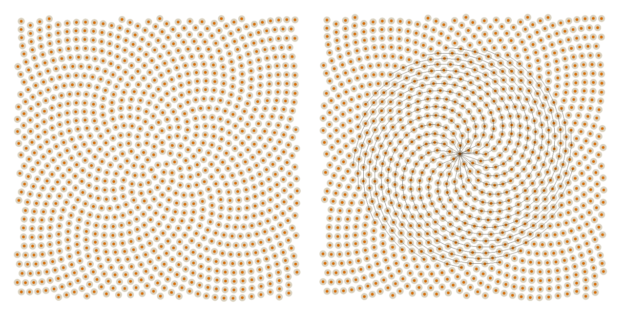
I had briefly considered using spirals when I was playing with patterns last week, but I wasn’t sure how to use them to get dual curvature, and I quickly moved on. Looking at the Fermat spirals, the sunflower model proposed by Vogel did look intriguing, so I put it into my test harness to see what it would look like:
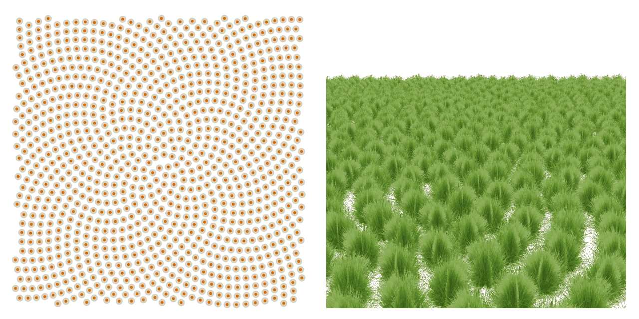
Unfortunately, as I suspected from looking at the pattern on Wikipedia, it turns out not to be a very good pattern for grass planting because it suffers from the same sort of “curved cornrow” artifacts as non-staggered concentric intersection. However, it does seem theoretically possible that one could devise a stagger pattern on top of it that would rectify this, much like how the staggered version fixed the concentric intersection’s cornrows.
That said, I have absolutely no idea what that pattern would be. Nothing sprang (sprung? springed, clearly) to mind when looking at the way the points were laid down. Basically the pattern adds one new point to each spiral every 21 iterations:
While it is easy to shift any given spiral in much the same way I shifted the concentric intersection pattern, I can’t say I know how much you would shift each point by, or whether you even want to shift on a spiral basis in the first place. I think it would take me a little while to study this pattern and understand how it works more deeply before I could recommend a good jitter, and that’s not something I have time to do at the moment. If anyone plays around with it and gets good results, I’d love to hear about it.
This is Not Real Grass
Several people commented that it would be a good idea to look at real grass and understand how it grows in order to better design the pattern for planting it. While I commend this suggestion for being exactly how one should go about solving a different problem, unfortunately it is not relevant for solving this problem.
The reason is because this is not a simulation of actual grass. Actual grass grows in actual blades whose numbers vastly outstrip the number we could feasibly render on the target platforms of The Witness. The pattern I am trying to create isn’t at all related to how real grass grows because it’s not trying to mimic that pattern. It’s simply trying to figure out a way to best cover an area without you noticing the places that aren’t covered. The fact that there’s some grass on the texture map is about the extent to which the properties of grass are related to this endeavor.
However, I will point out that I did write some grass generation code for an off-line rendering project many years ago (circa 2006) where I did do exactly what was being suggested. I took my camera outside and took pictures of various grasses around town myself, and looked at the clumping and clustering. That’s an article for another day, but I can say definitively that it greatly informed the biggest feature of that algorithm that I had not thought to do previously, which was to focus on the fact that grasses in human-controlled environments mostly grows sideways, not upward, and capturing that goes a long way towards making something that looks like a “lawn”.
Back on Track
I do apologize for spending two weeks now on something that, technically, is not even related to The Witness apart from the fact that it motivated me to look into it. Next week, I will properly resume talking about things that are actually in The Witness, and will include the previously promised riveting video footage of a place — and I am not making this up for effect — called CaseyTown. How can you pass up an opportunity to (virtually) visit a place called CaseyTown? I suspect you cannot pass up such an opportunity, and as such, I will see you back here next week for another wonderful Witness Wednesday.